Hydraulic Brakes for Cranes | Industrial Lifting Equipment | 2025 Complete Safety Guide
What Are Hydraulic Brakes in Crane Applications
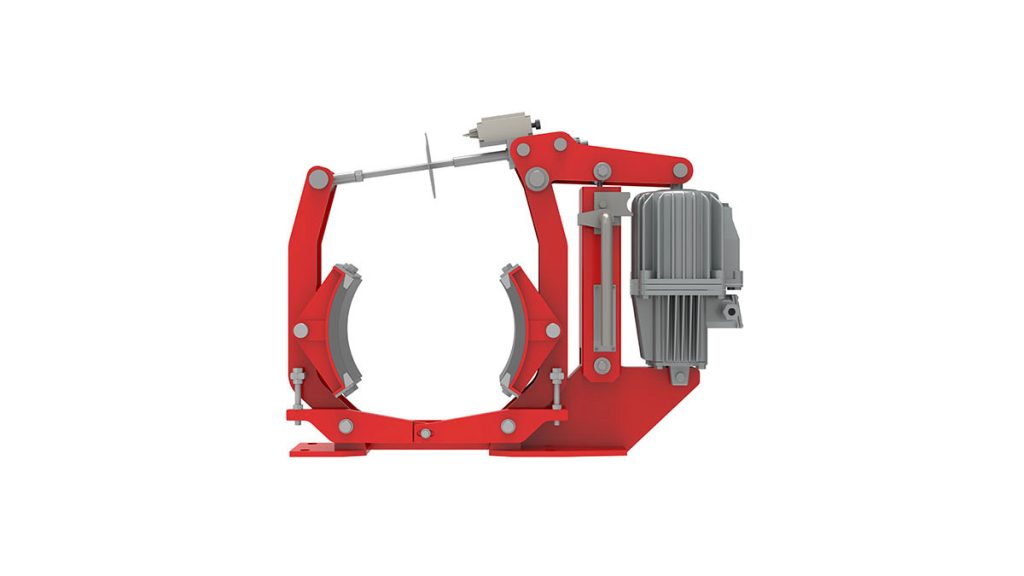
Hydraulic brakes for cranes represent critical safety systems that control load movement and provide emergency stopping capability in lifting operations. These systems use pressurized hydraulic fluid to release spring-applied friction elements. The design creates a fail-safe mechanism. When hydraulic pressure drops due to power loss or system failure, powerful springs automatically engage the brake. This prevents uncontrolled load descent and equipment movement. Modern crane hydraulic brakes handle loads from 5 tons to over 500 tons across bridge cranes, tower cranes, mobile cranes, and port equipment.
The fundamental operating principle differs significantly from automotive brake systems. Crane brakes remain engaged by default through spring force. Hydraulic pressure must be actively applied to release the brake and allow motion. This spring-applied, hydraulically-released (SAHR) configuration ensures automatic braking during any system failure. Operating pressures typically range from 10-25 MPa depending on brake size and torque requirements. The system generates braking torque from 500 Nm for small hoists to over 50,000 Nm for large container cranes.
According to crane safety research, properly maintained hydraulic brake systems prevent 85-92% of potential load-drop incidents in industrial lifting operations. The global crane brake system market reached $890 million in 2024 with projected 5.6% annual growth through 2030. This expansion reflects increasing construction activity, port automation adoption, and stricter safety regulations worldwide. Understanding brake system architecture, selection criteria, and maintenance requirements ensures safe crane operations across all applications.
Core Components of Crane Hydraulic Brake Systems
Spring Pack and Brake Frame Assembly
The spring pack provides the mechanical force that applies the brake. Multiple heavy-duty compression springs generate consistent pressure throughout the friction material lifecycle. Spring force typically ranges from 15-40 kN per spring depending on required brake torque. Engineers size spring stacks to produce 125-150% of calculated holding torque requirements. This safety margin compensates for friction material wear, temperature effects, and environmental factors affecting brake performance.
The brake frame houses all internal components and provides mounting interface to crane structures. Cast iron or fabricated steel construction withstands operational forces and environmental exposure. Frame designs incorporate cooling fins increasing surface area by 300-500% compared to smooth housings. This enhanced heat dissipation proves critical during frequent duty cycles. Some heavy-duty applications require forced-air or water cooling systems. These maintain acceptable operating temperatures during continuous load lowering operations.
A tower crane manufacturer transitioned to optimized spring pack designs in 2023. New compression springs with improved metallurgy extended service life from 12,000 to 18,500 operating hours. Field data from 340 cranes showed spring-related failures decreased 82%. Customer maintenance costs dropped $1,850 per crane annually. The improved spring design added $180 to manufacturing costs. However, warranty savings and customer satisfaction gains justified the investment across the entire product line.
Hydraulic Release Mechanism
Hydraulic cylinders or pistons compress the spring pack when pressure is applied. This releases friction elements allowing rotation. The hydraulic system must generate sufficient force to overcome spring preload plus additional forces from return springs and seal friction. Typical release pressures range from 12-20 MPa in industrial crane applications. Seal designs prevent fluid leakage while minimizing friction. Multi-lip seals provide redundancy preventing sudden pressure loss.
Hydraulic circuits supplying brake release pressure operate independently from main crane motion systems. Dedicated pumps, valves, and accumulators ensure brake operation even during primary system failures. Accumulator systems store pressurized fluid providing backup brake release capability. Properly sized accumulators maintain 10-20 brake release cycles after pump failure. This allows operators to safely lower loads and park equipment during hydraulic system malfunctions.
Proportional control valves enable variable brake torque adjustment during load handling. Pressure transducers continuously monitor actual release pressure. Control systems compare measured values against commanded setpoints. Deviations exceeding tolerance thresholds trigger alarms or automatic shutdown sequences. A container port operator upgraded brake control systems on 12 ship-to-shore cranes. New proportional valves improved positioning accuracy by 40%. Container handling speed increased 12%. The system cost $180,000 per crane. Productivity improvements generated $240,000 annual value per crane achieving 9-month payback.
Friction Materials and Wear Components
Friction materials generate the stopping force by converting kinetic energy to heat. Material selection depends on duty cycle, operating environment, and performance requirements. Organic materials using resin-bonded fibers suit light-duty indoor applications. Semi-metallic formulations incorporating copper and iron particles provide better heat resistance for moderate-duty cycles. Sintered metal materials offer maximum performance for heavy-duty continuous operation. Friction coefficients range from 0.35-0.55 depending on composition and operating conditions.
Friction material thickness typically ranges from 12-25mm when new. Manufacturers specify minimum thickness limits usually 3-5mm. Operating beyond minimum thickness risks brake failure and potential accidents. Wear rates vary dramatically based on duty cycle and operating practices. Light-duty indoor cranes may achieve 15,000+ operating hours per friction set. Heavy-duty outdoor cranes in harsh environments may require replacement every 2,500-4,000 hours. Proper maintenance tracking prevents premature wear-out while maximizing component utilization.
A steel mill operates 8 overhead cranes handling critical production materials. These cranes implemented structured friction material monitoring in 2022. Maintenance staff measure and document brake pad thickness every 500 operating hours. Database tracking identifies wear patterns and predicts replacement timing. Component utilization improved from 6,200 to 8,800 hours average. Emergency brake failures decreased from 3.2 to 0.4 incidents annually. The enhanced monitoring program cost $12,000 annually. Avoided downtime and improved reliability generated $185,000 annual value.
Monitoring and Safety Systems
Modern crane installations incorporate comprehensive brake monitoring. Pressure sensors verify hydraulic release pressure at each brake location. Low-pressure alarms indicate system problems requiring immediate attention. Temperature sensors detect overheating from excessive duty cycles or cooling system failures. Wear sensors provide continuous friction material thickness monitoring. Some advanced systems measure actual brake torque through load cells or strain gauges.
Integration with crane control systems enables sophisticated safety functions. Automatic brake engagement prevents load drift during positioning operations. Anti-two-block systems apply brakes preventing hook-to-boom contact. Overload protection engages brakes refusing lifts exceeding rated capacity. Data logging records all brake operations creating audit trails for maintenance and incident investigation. According to lifting equipment safety standards, brake monitoring systems reduce serious incidents by 45-60% in industrial crane operations.
An offshore crane operator serving oil platforms installed comprehensive brake monitoring on 8 pedestal cranes. Systems tracked pressure, temperature, and wear continuously. Predictive analytics identified 14 developing problems over 2-year operations. Scheduled maintenance prevented 11 potential failures. This avoided estimated production losses exceeding $4.2 million. System investment totaled $95,000 per crane. Risk reduction and avoided losses justified costs within the first operational year.
Types of Hydraulic Brakes Used in Cranes
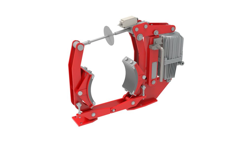
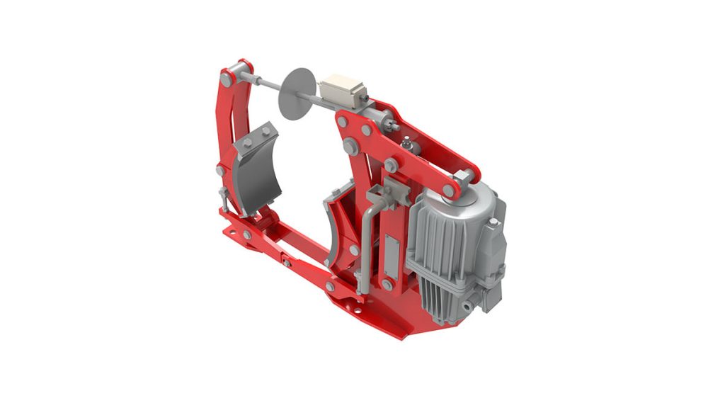
Drum Brakes for Traditional Crane Systems
Drum-type hydraulic brakes mount externally on rotating drums connected to hoist ropes or wheel axles. Curved brake shoes press against drum outer surface when spring force applies. Hydraulic pressure retracts shoes allowing rotation. Drum diameters range from 200mm for small hoists to 1,500mm for large ship-to-shore cranes. Brake shoe width typically measures 80-300mm depending on torque requirements. The simple design allows easy visual inspection and maintenance access.
Advantages include proven reliability, simple construction, and easy friction material replacement. Technicians can assess brake condition without complete disassembly. Disadvantages include environmental exposure and sensitivity to contamination. Dust, moisture, and corrosive atmospheres accelerate wear rates. Drum brakes suit indoor installations and moderate duty cycles. Many overhead crane manufacturers continue specifying drum brakes for standard industrial applications due to cost effectiveness and maintenance simplicity.
A manufacturing facility operates 15 overhead cranes with drum brake systems. Average friction material life reaches 8,500 operating hours under normal production schedules. Annual brake maintenance costs average $1,850 per crane including materials and labor. Unscheduled brake failures occur 0.4 times per crane annually. Overall reliability proves satisfactory for the application. The facility continues specifying drum brakes for new crane procurements. Parts availability and technician familiarity drive this decision.
Disc Brakes for Heavy-Duty Applications
Disc brake systems clamp hydraulically-released brake pads against rotating steel discs. The compact configuration delivers high torque capacity in minimal space. Enclosed designs protect friction surfaces from environmental contamination. Heat dissipation improves through larger cooling surface areas. Disc brakes dominate mobile cranes, tower cranes, and heavy-duty port equipment applications. Superior performance justifies higher initial costs in demanding environments.
Multiple disc assemblies increase torque capacity without enlarging overall dimensions. Three to five disc stacks are common in heavy cranes. Each disc pair generates independent braking torque. Total capacity equals the sum of individual disc contributions. Automatic wear compensation maintains constant air gap as pads wear. This ensures consistent brake torque throughout pad life. Disc brake service requires specialized tools. However, extended service intervals and superior reliability offset maintenance complexity.
A tower crane manufacturer transitioned from drum to disc brakes across their product range in 2022. Field reliability data from 340 cranes over 24 months showed significant improvements. Mean time between brake service increased from 1,800 to 4,200 operating hours. Unscheduled brake failures decreased 76% compared to previous drum brake designs. Customer feedback highlighted improved performance consistency. Development investment totaled $2.8 million. Warranty cost reductions exceeded $1.6 million annually justifying continued disc brake adoption.
Emergency and Redundant Brake Systems
Critical lifting applications require redundant brake systems providing backup stopping capability. Primary and secondary brakes operate on the same shaft with independent hydraulic circuits. Both brakes release for normal operation. Either brake alone provides sufficient holding capacity for rated loads. This configuration prevents catastrophic failures from single-component malfunctions. Nuclear facilities, hot metal handling, and personnel lifting applications mandate redundant brakes.
Combination systems may use different brake types for primary and secondary functions. Disc brakes provide primary working brakes. Drum brakes serve as backup holding brakes. This approach balances performance, reliability, and cost. Independent hydraulic circuits use separate pumps, valves, and accumulators. Complete circuit failure in one system does not affect the other. Cross-monitoring verifies both circuits maintain proper release pressure during operation.
A steel mill crane handling molten metal ladles implemented redundant brake systems in 2024. Each hoist received primary disc brakes and secondary drum brakes. Independent hydraulic circuits included dedicated accumulators maintaining 20-minute backup capacity. Over 12-month operations, two primary brake circuit failures occurred. Secondary brakes automatically maintained load control preventing incidents. Redundant design cost added 65% to brake expenses. However, safety improvements justified investment for this critical application.
Parking and Holding Brake Functions
Crane systems distinguish between service brakes for normal operations and parking brakes for static load holding. Service brakes modulate torque during load movement. Parking brakes maintain load position during extended shutdown periods. Some designs integrate all functions into single assemblies. Others employ separate systems for each function. Parking brake engagement requires zero load and stationary conditions. Interlocks prevent accidental disengagement under load.
Emergency brake circuits bypass normal controls applying full brake force instantly. Dedicated emergency buttons or automatic triggers activate emergency braking. Triggers include overload conditions, excessive speed, or safety system violations. Emergency engagement may cause load swinging or structural stress. According to crane operator training standards, proper brake system understanding reduces operator-error incidents by 35-50%.
A port authority operates 18 gantry cranes with integrated parking brake monitoring. Systems verify parking brake engagement before permitting maintenance mode access. This safety enhancement prevented 3 incidents over 5-year period. Previous procedures relied on operator verification alone. Automated monitoring eliminates human error risks. The monitoring system cost $8,500 per crane. Safety improvements and liability reduction justified this modest investment.
Crane Applications and Performance Requirements
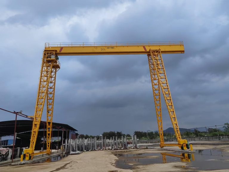
Overhead Bridge and Gantry Cranes
Industrial overhead cranes utilize hydraulic brakes on hoist, trolley, and bridge travel mechanisms. Hoist brakes must hold 125% of rated capacity with power off. This safety margin accounts for dynamic effects and component wear. Trolley and bridge travel brakes prevent uncontrolled movement on sloped runways. Brake torque calculations consider runway grade, equipment weight, and wind loads. Maximum grade capabilities typically range from 1-3% depending on brake sizing.
Duty cycle classification significantly affects brake selection. Class A infrequent service requires minimal heat dissipation. Class F continuous severe service demands premium friction materials and forced cooling. FEM and CMAA duty classifications provide standardized guidance. Typical overhead crane hoist brakes operate at 15-30% duty cycles. Bridge and trolley brakes see lighter duty at 5-15% cycles. Proper selection matching actual duty prevents premature failures.
An automotive manufacturing plant operates 24 overhead cranes supporting assembly operations. These handle 5-20 ton loads with frequent positioning movements. Brake systems use semi-metallic friction materials rated for moderate duty. Average component life reaches 12,000 operating hours before friction material replacement. Annual brake maintenance costs average $2,100 per crane. Unscheduled brake-related downtime occurs less than 0.3% of operating hours. Current specifications provide satisfactory performance and reliability.
Mobile and All-Terrain Cranes
Mobile crane hydraulic brakes operate on swing, hoist, and boom functions. Swing brakes control rotational movement during load positioning. Large friction surface areas dissipate substantial kinetic energy when stopping loaded booms. Hoist brakes provide load holding and controlled lowering capability. Load-sensing systems adjust brake release pressure based on actual hook loads. This maintains consistent lowering speeds regardless of load variations. Boom hoist brakes position telescoping sections or luffing jibs.
Swing brake torque requirements depend on boom length, load weight, and rotational inertia. Large mobile cranes handling 100+ ton capacities generate enormous rotational energy. Emergency swing stops must dissipate this energy without structural overload. According to mobile crane safety regulations, swing brake capacity must stop maximum-loaded boom within 3-5 degrees rotation under emergency conditions.
A crane rental company operates 45 mobile cranes with brake monitoring systems implemented in 2023. Wireless sensors track brake pressure and temperature on swing and hoist functions. Data analytics identified 8 cranes requiring early service preventing potential failures. Brake component life improved 18% through optimized maintenance scheduling. Insurance premiums decreased 12% based on demonstrated safety management. Total investment reached $520,000. Combined savings generated $340,000 annual value achieving 18-month payback.
Tower Cranes for Construction Sites
Tower crane brake systems face unique challenges from extreme heights and exposed conditions. Slewing brakes control cab and boom rotation. These handle substantial rotational inertia requiring large torque capacity. Hoist brakes provide load holding often with multiple-fall rope systems. Trolley brakes control load radius positioning along the boom. Wind-induced loads significantly impact brake requirements at heights exceeding 50 meters.
Cold weather operation affects brake performance substantially. Hydraulic fluid viscosity increases reducing brake release response. Friction material characteristics change with temperature. Some materials demonstrate reduced coefficients below -10°C. Cold-weather packages include heated hydraulic reservoirs and insulated brake housings. Friction materials qualified for low-temperature operation maintain consistent performance. European manufacturers routinely specify cold-weather packages for Nordic markets.
A construction contractor operates tower cranes in Arctic conditions. Initial commissioning revealed brake problems in -25°C temperatures. Brake release times exceeded acceptable ranges. Heating systems were retrofitted to hydraulic reservoirs and brake housings. Cold-weather friction materials replaced standard specifications. After modifications, systems operated reliably from -35°C to +35°C. Retrofit cost $18,000 per crane. This prevented project delays costing $500,000+ through improved reliability. Cold-weather specifications became standard for subsequent Arctic projects.
Port Equipment and Container Handling
Ship-to-shore cranes represent the most demanding crane brake applications. These handle 40-50 ton containers at extreme duty cycles. Hoist brakes dissipate 100-150 kW continuously during container lowering. Gantry travel brakes control 1,000+ ton crane movement along dock railways. Trolley systems span 50+ meter booms requiring positioning within 50mm tolerances. Brake performance directly impacts port throughput and vessel turnaround times.
Automated container terminals push brake systems to operational limits. Cranes operate continuously 20+ hours daily without human intervention. Reliability requirements exceed 99.5% availability. Predictive maintenance systems monitor brake parameters continuously. Automated diagnostics schedule maintenance during minimal-impact windows. Remote monitoring allows engineering support from manufacturer facilities thousands of kilometers away.
A major Asian port operates 28 automated ship-to-shore cranes handling 3.2 million containers annually. Advanced brake monitoring tracks temperature, pressure, and wear on all functions. Machine learning algorithms predict remaining component life with 95% accuracy. Maintenance scheduling optimizes part replacement minimizing operational impact. Over 3-year operations, unscheduled brake failures decreased 88% compared to reactive maintenance. Average crane availability improved from 96.8% to 99.3%. Monitoring system investment totaled $4.2 million. Productivity improvements generated $18+ million annual value.
Selection Criteria and Engineering Specifications
Load Capacity and Safety Factor Requirements
Brake torque capacity must exceed maximum holding requirements with appropriate safety factors. Calculate holding torque considering rated load, rope drum diameter, and gear reduction ratios. Apply minimum 125% safety factor for static holding. Dynamic braking during load lowering requires additional capacity. Friction material fade during extended lowering necessitates conservative sizing. Heavy loads descending from extreme heights generate substantial thermal energy requiring premium specifications.
Engineering calculations verify brake capacity across all operating scenarios. Maximum static load holding represents baseline requirements. Sustained lowering at rated capacity establishes thermal dissipation needs. Emergency stopping from maximum operating speed determines peak torque and energy absorption. Each scenario may drive sizing in different applications. Conservative engineers size brakes meeting all requirements with margin. Cost-optimized designs may specify separate emergency and service brake systems.
A shipyard engineer designed heavy-lift systems handling 300-ton loads. Hoist brake calculations required 45,000 Nm holding torque with 150% safety factor. Thermal analysis during sustained lowering showed 180 kW heat dissipation. Standard catalog brakes proved inadequate. Custom brake assemblies with forced air cooling provided required capacity. Engineering investment totaled $85,000 for design and testing. Custom brakes cost $240,000 per crane versus $120,000 for inadequate standard units. Proper sizing prevented potential catastrophic failures justifying premium investment.
Duty Cycle and Thermal Analysis
Duty cycle classification determines required thermal capacity and cooling provisions. FEM and CMAA classifications provide standardized duty ratings. Light-duty permits 15-25% duty cycles with natural convection cooling. Heavy-duty requires 40-60% duty cycles necessitating enhanced cooling. Extreme-duty exceeds 60% requiring forced cooling systems. Accurate duty cycle estimation prevents premature failures from thermal overload.
Thermal calculations consider heat generation rate, cooling surface area, and ambient temperature. Steady-state analysis determines maximum continuous operating temperature. Transient analysis verifies temperature rise during peak duty cycles remains within limits. Friction material temperature limits range from 200-250°C for organic materials to 350-400°C for sintered metals. Hydraulic fluid degradation accelerates above 80°C requiring cooling or oversized reservoirs.
An aluminum smelter operates overhead cranes in 45°C ambient temperatures handling molten metal. Initial brake specifications proved inadequate. Friction material temperatures exceeded 280°C causing rapid degradation. Brake life averaged only 1,200 hours versus 8,000-hour expectations. Forced-air cooling systems were retrofitted to all hoist brakes. Operating temperatures decreased to 180°C maximum. Friction material life improved to 9,500 hours exceeding targets. Cooling retrofit cost $15,000 per crane eliminating frequent failures and safety risks.
Environmental Conditions and Protection Requirements
Operating environment significantly influences brake specification and reliability. Indoor climate-controlled facilities require minimal environmental protection. Outdoor installations demand weather sealing against rain, snow, and temperature extremes. Corrosive atmospheres in chemical plants or coastal ports necessitate stainless steel components. Explosive atmospheres require certified equipment preventing ignition sources.
Temperature extremes affect hydraulic fluid, friction materials, and seal materials. Arctic applications require synthetic fluids maintaining viscosity to -40°C. High-temperature environments above 50°C need heat-resistant seals and premium fluids. Friction materials must maintain consistent coefficients across temperature ranges. Dust and particulate contamination require sealed designs with positive-pressure ventilation. Salt spray in coastal environments accelerates corrosion demanding protective coatings.
A mining company operates cranes in desert environments with 50°C daytime and -5°C nighttime temperatures. Standard components experienced rapid seal deterioration and friction material degradation. Specialized brake packages included high-temperature seals, desert-rated friction materials, and environmental enclosures. Component life improved from 2,400 to 6,800 operating hours. Initial equipment cost increased 35% for environmental specifications. Reduced maintenance generated 3:1 return on investment over equipment lifecycle.
Regulatory Compliance and Safety Standards
Crane brake systems must comply with applicable safety regulations and industry standards. OSHA regulations mandate specific brake capacities and safety factors. ASME B30 series standards provide detailed requirements for various crane types. European FEM and ISO standards govern equipment in international markets. Certification and testing requirements vary by jurisdiction and application. Design engineers must understand applicable requirements ensuring compliance.
Testing and validation procedures verify brake performance meets specifications. Static load holding tests confirm capacity at 125% rated load. Dynamic braking tests measure stopping distances under loaded conditions. Thermal endurance testing validates continuous duty cycle capability. Brake release time measurements ensure responsive operation. Third-party certification may be required for specific applications. Documentation includes design calculations, test results, and maintenance procedures.
A crane manufacturer developed new product line targeting North American and European markets. Design teams worked with regulatory consultants ensuring OSHA and FEM compliance. This required larger safety factors and extensive testing. Engineering costs increased $850,000 for regulatory compliance work. However, dual-certification enabled market access worth $40+ million annually. Regulatory expertise became competitive advantage simplifying customer approval processes.
Maintenance Procedures and Best Practices
Inspection Schedules and Documentation
Systematic brake inspection prevents failures and maintains optimal performance. Daily pre-operational checks verify hydraulic pressure reaches specification. Operators report unusual noises, vibrations, or inconsistent response. Weekly inspections examine friction material thickness and surface conditions. Measure remaining material against minimum specifications. Most applications require replacement at 3-5mm remaining thickness depending on design.
Monthly detailed inspections include hydraulic fluid sampling and analysis. Test fluid for viscosity, contamination, and moisture content. Moisture levels exceeding 500 PPM accelerate corrosion requiring immediate replacement. Particulate contamination indicates component wear requiring investigation. Quarterly inspections measure brake response times and verify proper adjustment. Annual comprehensive inspections include complete disassembly, cleaning, and component measurement. Document all findings creating historical records identifying trends.
A steel mill operates 8 overhead cranes handling critical production loads. Structured brake maintenance program implementation in 2022 followed manufacturer recommendations with enhanced documentation. Brake-related unscheduled downtime decreased 73% over 2-year period. Component life improved 25% through early problem detection. Maintenance labor costs increased $28,000 annually for enhanced inspections. However, avoided downtime and extended component life generated $185,000 annual value. The maintenance program proved highly cost-effective while improving safety.
Friction Material Replacement Procedures
Friction material replacement represents the most frequent brake service. Measure material thickness before disassembly documenting wear rates. Remove spring pressure using proper tooling preventing injury from stored energy. Inspect friction surfaces for cracking, glazing, or contamination. Surface contamination from oil or hydraulic fluid requires thorough cleaning and source repair. Replace all friction materials and springs during overhaul. Mixing worn and new components causes uneven performance and premature failure.
Brake drum or disc surface condition affects friction material life significantly. Measure surface runout and thickness variation. Runout exceeding 0.5mm causes vibration and uneven wear. Machine or replace drums/discs showing excessive wear or surface damage. Proper surface finish ensures optimal friction contact. Finish too smooth causes glazing. Finish too rough accelerates wear. Follow manufacturer specifications for surface preparation.
Component replacement extends beyond friction materials. Inspect and replace hydraulic seals showing any deterioration. Measure spring free height and compression force. Weak springs reduce brake torque compromising safety. Replace spring sets maintaining matched characteristics. Brake overhauls typically occur at 8,000-15,000 operating hours depending on duty cycle. Skilled technicians complete overhauls in 4-8 hours per unit depending on complexity.
Hydraulic System Service and Fluid Testing
Hydraulic fluid quality directly impacts brake reliability and performance. Annual fluid sampling identifies contamination requiring action. Viscosity changes indicate thermal degradation or contamination. Particle counting reveals internal wear patterns. Moisture content above 500 PPM promotes corrosion and reduces fluid life. Complete fluid replacement every 2-3 years maintains optimal performance regardless of testing results.
Hydraulic filter maintenance prevents contamination from damaging components. Replace filters according to differential pressure indicators or scheduled intervals. Bypass indicators show when filters reach capacity requiring immediate replacement. Contaminated fluid causes valve sticking, seal deterioration, and inconsistent operation. System flushing may be necessary after major component failures. Proper flushing removes contaminants preventing repeat failures.
Accumulator systems providing backup brake release require periodic inspection. Measure gas precharge pressure with hydraulic pressure relieved. Incorrect precharge reduces accumulator effectiveness compromising backup capacity. Bladder or piston seals eventually deteriorate requiring accumulator rebuild. Test capacity by cycling brakes with pump disabled. Insufficient backup cycles indicate service required. A port crane operator implemented accumulator testing into quarterly procedures. This prevented 2 potential brake failures over 4-year period when accumulators showed degraded capacity.
Troubleshooting Common Brake Problems
Slow brake release indicates hydraulic pressure problems or mechanical binding. Verify hydraulic pressure at brake using calibrated gauges. Low pressure points to pump problems, valve failures, or hydraulic leaks. Mechanical binding results from corrosion, misalignment, or contamination. Disassembly and inspection identifies binding sources requiring correction. Temperature monitoring during operation identifies cooling problems causing friction fade.
Inconsistent brake torque suggests friction material problems or air in hydraulic system. Glazed friction surfaces reduce friction coefficients. Contamination from hydraulic fluid or lubricants causes severe torque loss. Oil-contaminated friction materials require replacement along with source repair. Air in hydraulic circuits creates spongy response and reduced torque. Proper bleeding procedures remove trapped air restoring normal performance.
Excessive brake wear indicates problems beyond normal operation. Verify brake sizing adequately meets application requirements. Undersized brakes operate beyond thermal capacity accelerating wear. Improper adjustment causes continuous friction contact during released condition. This generates unnecessary heat and wear. Contamination accelerates abrasive wear requiring environmental protection improvements. Systematic failure analysis identifies root causes enabling effective corrective actions.
Price Disclaimer: All pricing information represents approximate market rates as of 2025. Actual costs vary based on crane type, capacity, specifications, labor rates, and location. Consult qualified service providers and manufacturers for current quotations specific to your crane equipment.
Technical Disclaimer: This guide provides general technical information for educational purposes. Specific brake service procedures vary by crane manufacturer and model. Always consult manufacturer service manuals and follow all safety procedures. Crane brake work requires qualified technicians with proper training, tools, and certifications. Improper brake service creates serious safety hazards including potential load drops. Contact professional service providers for brake system diagnosis, repair, and maintenance.
Conclusion: Implementing Effective Crane Brake Management
Hydraulic brake systems deliver critical safety and control functions across all crane and lifting equipment types. Understanding system architecture, performance requirements, and maintenance procedures enables optimal brake management. Modern brake monitoring provides early warning of developing problems enabling proactive maintenance. Regulatory compliance ensures equipment meets safety standards protecting personnel and property.
Organizations operating crane fleets benefit from structured brake management programs. Scheduled inspections identify wear before failures occur. Quality component selection and proper service extend brake system life. Comprehensive technician training ensures proper maintenance techniques. Data-driven scheduling optimizes resources while maintaining safety standards. Effective brake management reduces accidents, prevents downtime, and demonstrates regulatory compliance.
Free Technical Consultation: Need assistance with crane brake system selection, troubleshooting, or maintenance program development? Experienced crane engineers and brake specialists provide complimentary consultations covering system design, component selection, regulatory compliance, and service procedures. Contact technical support teams to discuss performance requirements and receive expert recommendations ensuring optimal brake system performance and safety.