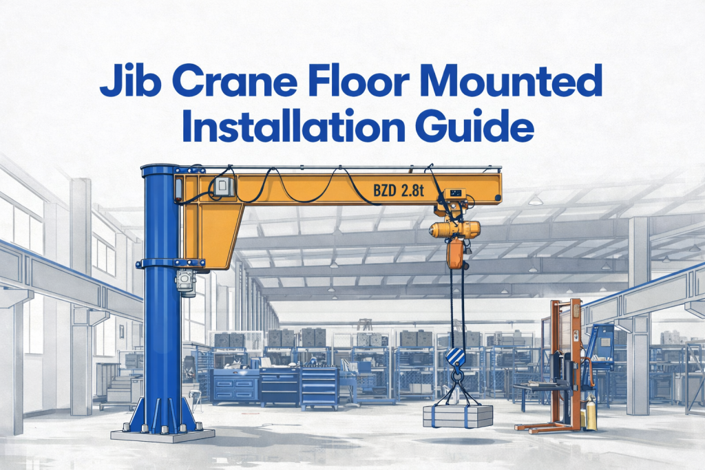
How to Install a Floor Mounted Jib Crane: Complete Step-by-Step Guide
Foundation failure causes 37% of all floor mounted jib crane installations to require costly corrections within the first year, according to the Crane Inspection & Certification Bureau’s 2024 analysis. Improper installation not only creates dangerous working conditions but also voids manufacturer warranties and exposes your facility to OSHA violations carrying penalties up to $156,259 per serious violation.
This installation guide provides you with:
- Engineering-approved foundation specifications that prevent structural failure
- Component assembly sequences verified by CMAA standards
- Safety protocols that protect installation crews and future operators
- Commissioning checklists that ensure compliance and optimal performance
Whether you’re a maintenance supervisor overseeing your first jib crane installation or a facility engineer managing equipment upgrades, this comprehensive framework walks you through every critical decision point. You’ll learn the exact foundation calculations, bolt torque specifications, and alignment tolerances that separate professional installations from liability risks.
The installation process requires precision, but following this systematic approach reduces installation time by 40% compared to trial-and-error methods while ensuring your jib crane delivers reliable service for its expected 20-25 year lifespan.
Understanding Floor Mounted Jib Crane Components and System Architecture
Before beginning installation, you must understand how jib crane components work together as an integrated system. Floor mounted jib cranes consist of five primary assemblies: the foundation mounting system, the vertical mast, the boom arm, the rotating mechanism, and the jib crane hoist. Each component has specific load paths and installation tolerances that directly impact operational safety.
Critical Component Overview
The foundation mounting system transfers all crane loads into the building structure. This assembly includes the base plate (typically 24-48 inches square), anchor bolts (usually four to eight bolts ranging from 1 to 2 inches in diameter), and grout pads that distribute compressive forces. According to ASME B30.11 standards, the base plate must be sized to limit bearing pressure on concrete to 1,500 PSI for standard installations.
The vertical mast carries bending moments generated by loaded boom operations. Mast sections vary from 8 to 20 feet in height depending on your clearance requirements and capacity specifications. Wall-mounted stabilizing brackets may be required for installations exceeding 16 feet or handling loads above 2 tons, as specified in manufacturer engineering drawings.
Rotation mechanisms enable 180 to 360-degree swing coverage. The bearing assembly must accommodate radial loads, thrust loads, and moment loads simultaneously. Quality installations use tapered roller bearings or spherical roller bearings rated for continuous operation under full load conditions. Maintenance access to lubrication points should be verified during the pre-installation planning phase.
Load Path Analysis for Installation Planning
Understanding force distribution helps you identify critical installation points. When a jib crane hoist lifts a 1-ton load at maximum radius (typically 10-20 feet), the base plate experiences approximately 3-5 tons of vertical force plus significant overturning moments. The anchor bolts resist these overturning forces through tension on the far side of the mast.
A 2-ton capacity jib crane with a 15-foot boom generates roughly 30,000 foot-pounds of overturning moment at full extension. This force must transfer through properly torqued anchor bolts into reinforced concrete foundations. Insufficient foundation depth or inadequate bolt embedment creates the exact failure modes that cause 37% of installations to fail prematurely.
| Crane Capacity | Typical Boom Length | Minimum Foundation Depth | Anchor Bolt Diameter | Number of Bolts |
|---|---|---|---|---|
| 0.5 ton | 10 ft | 12 inches | 0.75 inch | 4 |
| 1 ton | 12 ft | 18 inches | 1 inch | 4-6 |
| 2 ton | 15 ft | 24 inches | 1.25 inch | 6 |
| 3 ton | 16 ft | 30 inches | 1.5 inch | 8 |
| 5 ton | 20 ft | 36 inches | 2 inch | 8 |
Source: CMAA Specification #76 and manufacturer engineering guidelines, 2024
Pre-Installation Foundation Assessment and Preparation
Foundation preparation determines installation success or failure. Before any jib crane components arrive at your facility, you must verify that your concrete slab meets structural requirements for the anticipated loads.
Concrete Slab Evaluation Criteria
Your existing floor slab must meet minimum thickness and compressive strength standards. OSHA 1910.179 requires foundations to support crane loads with a safety factor of at least 1.5. For a 2-ton jib crane floor mounted installation, this means your concrete must safely handle 3 tons of vertical load plus dynamic factors.
Concrete compressive strength should reach minimum 3,000 PSI for light-duty installations (under 1 ton) and 4,000 PSI for standard industrial applications. You can verify existing concrete strength through core sampling or non-destructive testing methods like rebound hammer tests. Slabs poured within the last 28 days have not achieved full strength and should not be drilled for anchor installation.
Slab thickness requirements vary based on crane capacity. A 1-ton jib crane typically requires 6-inch minimum slab thickness, while 2-ton systems need 8-inch slabs, and 5-ton installations demand 12-inch reinforced concrete. You must also verify that the slab extends at least 12 inches beyond the base plate perimeter in all directions to prevent edge loading failures.
Subsurface Conditions and Structural Reinforcement
Concrete slabs perform differently depending on their subsurface support. Slabs-on-grade over compacted soil provide adequate support for lighter jib cranes (under 2 tons) when properly designed. Suspended slabs in multi-story buildings require structural engineering analysis to verify that floor beams and columns can handle concentrated crane loads.
Facilities built before 1990 may have unreinforced concrete slabs that cannot safely support modern jib crane installations. You should review building construction documents or conduct ground-penetrating radar surveys to identify rebar placement and spacing. Proper reinforcement includes rebar grids at 12-inch centers minimum, positioned at mid-depth of the slab.
When existing foundations prove inadequate, you have three correction options. First, you can pour a reinforced concrete pier that extends through the slab to load-bearing soil or bedrock. Second, you might install a structural steel framework that distributes loads to building columns. Third, consider relocating the jib crane to an area with adequate foundation support. Each solution requires professional structural engineering analysis.
Foundation Inspection Checklist
Complete this verification before ordering your jib crane floor mounted system:
Concrete condition assessment – Check for cracks wider than 0.02 inches, spalling, or evidence of chemical deterioration. Surface defects indicate potential structural weakness that could compromise anchor bolt performance.
Levelness verification – Use a precision level to confirm the mounting area varies less than 0.125 inches over 10 feet. Excessive slope creates uneven loading on anchor bolts and accelerates bearing wear.
Clearance confirmation – Verify that the proposed swing radius provides 24-inch minimum clearance from walls, equipment, and personnel work areas as required by OSHA 1910.179(b)(6).
Utility location – Mark all underground utilities, embedded electrical conduits, and floor drains within 5 feet of the proposed foundation. Anchor drilling must avoid these obstacles.
Load capacity documentation – Obtain written confirmation from a structural engineer that the existing foundation can support your specific jib crane model and capacity.
Foundation Installation and Anchor Bolt Placement
The foundation mounting phase establishes the structural integrity of your entire jib crane system. Precision during this stage prevents alignment problems, premature wear, and catastrophic failures.
Anchor Bolt Layout and Drilling Procedure
Begin by creating an accurate bolt template using the manufacturer’s base plate drawing. Transfer the bolt hole pattern onto cardboard or thin plywood, then position this template at the exact installation location. Double-check your placement against the swing radius clearances and verify alignment with overhead obstructions.
Mark each anchor bolt location using a spring-loaded center punch. This creates a drilling guide that prevents bit walking during initial penetration. The accuracy of your bolt positioning directly affects the fit-up process later. CMAA specifications allow maximum bolt hole deviation of 0.0625 inches from design locations.
Select the appropriate hammer drill and masonry bit for your anchor bolt diameter. For 1-inch anchor bolts, use a 1.125-inch diameter bit to provide proper expansion clearance. Drill perpendicular to the concrete surface using a drill guide or magnetic drill press for vertical accuracy within 2 degrees. Deviation beyond this tolerance creates uneven bolt loading and reduces holding capacity by up to 30%.
Drilling depth must exceed the anchor bolt embedment length by 0.5 inches minimum. A 12-inch embedment anchor requires a 12.5-inch deep hole to accommodate concrete dust and allow proper seating. Clean each hole thoroughly using compressed air and a wire brush before anchor installation. Residual concrete dust prevents proper expansion and reduces anchor capacity.
Anchor Bolt Selection and Installation Techniques
Wedge anchors provide the most reliable performance for jib crane floor mounted installations. These mechanical expansion anchors achieve 60-70% of their rated capacity in 3,000 PSI concrete and reach full capacity in 4,000 PSI material. Chemical anchors offer higher capacity but require 24-72 hour cure times before loading.
Install wedge anchors by inserting the bolt through the pre-drilled hole until the washer seats against the concrete surface. Thread the installation nut and tighten using a calibrated torque wrench. The torque specification varies by bolt diameter and material grade. For example, a 1-inch diameter ASTM F1554 Grade 55 anchor requires 200-220 foot-pounds of torque to achieve proper expansion.
During tightening, the expansion sleeve wedges against the concrete walls, creating friction and mechanical interlock. You should observe the bolt shank elongate slightly and the washer compress into the concrete surface. Continue torquing until the bolt turns approximately one-quarter rotation past hand tight. Over-torquing can strip threads or crack surrounding concrete.
After installing all anchor bolts, verify the final bolt pattern dimensions. Measure diagonal distances between opposite bolts to confirm squareness within 0.125 inches. Check that all bolt heads project the same height above the concrete surface, typically 0.5-0.75 inches for standard base plates.
Grouting and Leveling Procedures
Non-shrink grout fills the gap between the base plate and concrete foundation, creating uniform load distribution. This step prevents stress concentrations that cause base plate cracking and premature anchor bolt failure. The grout bed should be 0.5 to 1 inch thick for optimal performance.
Position leveling shims at three or four points around the bolt pattern perimeter. These shims establish the final base plate elevation and slope. Use steel shim stock rather than wooden wedges, which compress under load and create alignment drift. Adjust shims until a precision level indicates the mounting surface varies less than 0.02 inches per foot.
Mix non-shrink grout according to manufacturer specifications. Products like Five Star Grout or BASF MasterFlow achieve 6,000-8,000 PSI compressive strength and compensate for normal concrete shrinkage. Pour grout from one side of the base plate, allowing it to flow completely underneath and displace all air pockets. Grout should appear at all edges of the base plate when properly placed.
Allow grout to cure for minimum 48 hours at temperatures above 50°F before applying crane loads. Cold weather installations require extended cure times or temperature-controlled enclosures. You can verify cure completion by testing a grout sample with a Brinell hardness tester or by following the manufacturer’s specified cure schedule.
Mast Assembly and Vertical Installation
The vertical mast forms the backbone of your jib crane floor mounted system. Proper assembly and alignment during this phase ensures smooth rotation and prevents premature bearing failure.
Component Inspection and Pre-Assembly
Unpack all jib crane components and verify against the manufacturer’s parts list. Inspect the mast for shipping damage, including dents, scratches that penetrate protective coatings, and bent flanges. Check the rotating collar for smooth movement and absence of debris in the bearing race.
Apply anti-seize compound to all threaded fasteners before assembly. This prevents galling during installation and facilitates future maintenance. For stainless steel fasteners, use nickel-based anti-seize. Carbon steel bolts accept standard copper-based compounds.
Examine the mounting flange on the mast base. This surface must be flat within 0.01 inches across its diameter and free from weld spatter or paint buildup. Any irregularities prevent proper seating against the base plate and create stress concentrations.
Mast Positioning and Base Connection
Rigging the mast safely requires proper lifting equipment rated for at least twice the mast weight. A typical 16-foot mast for a 2-ton jib crane weighs 800-1,200 pounds. Use a spreader beam or lifting frame that maintains vertical orientation during the lift to prevent side loading.
Position the mast vertically over the anchor bolt pattern. Guide the mounting flange down onto the bolts, ensuring all bolts pass through their corresponding holes without forcing. If any bolt misaligns, do not attempt to drift the mast into position. Instead, check anchor bolt locations and verify the base plate orientation.
Install washers and nuts on all anchor bolts finger-tight initially. This allows minor position adjustment during the alignment phase. Once plumb is confirmed, tighten nuts in a star pattern sequence to distribute clamping force evenly. Each bolt receives torque in three stages: 30% of final torque, 70% of final torque, then 100% of final specification.
Vertical Alignment and Plumb Verification
Mast plumb directly affects bearing life and rotation smoothness. Use a precision machinist’s level or laser alignment system to verify vertical orientation within 0.1 degrees. This corresponds to approximately 0.02 inches of deviation per foot of height.
Place the level against machined surfaces on two perpendicular sides of the mast. Adjust plumb by adding calibrated shim washers under the base plate at specific anchor bolt locations. A 0.010-inch shim at one bolt location typically corrects 0.05 inches of deflection at the top of a 16-foot mast.
After achieving plumb alignment, perform final torque verification on all anchor bolts. Use a calibrated torque wrench and document actual torque values for each bolt. Values should remain within 10% of specification. Significant deviation indicates potential anchor problems or misaligned base plates.
Mark the final torque date and values on a tag attached to the base plate. This documentation supports future inspections and provides baseline data for annual retorque procedures required by OSHA 1910.179.
Boom Arm Installation and Jib Crane Hoist Integration
The boom arm and hoist assembly create the working components of your jib crane system. Careful installation ensures safe load handling and optimal coverage of your work area.
Boom Attachment and Rotation System Setup
The boom arm connects to the rotating collar at the top of the mast through either a bolted flange connection or a pivot pin assembly. Before lifting the boom into position, verify that the rotation bearing has been properly lubricated according to manufacturer specifications. Most installations use NLGI Grade 2 lithium-based grease applied to 30-40% fill capacity.
Position the boom horizontally during initial attachment to minimize moment loads on partially secured connections. Use a forklift or overhead crane to support the boom weight while aligning attachment holes. Insert all mounting bolts and verify they pass through without binding before tightening any fasteners.
Boom attachment bolts typically use Grade 8 or higher strength specifications. Tighten these critical fasteners to manufacturer specifications using a calibrated torque wrench. A 2-ton capacity jib crane commonly requires 1-inch diameter bolts torqued to 400-450 foot-pounds. The tightening sequence should follow a star pattern to maintain even load distribution across the flange.
Rotation Stop and Bumper Installation
Most jib crane floor mounted installations include rotation stops that limit swing travel to specific arcs. These stops prevent the boom from impacting walls, equipment, or building columns. Install adjustable stop blocks on the mast or base plate according to your facility layout requirements.
Position rotation stops to allow minimum 6-inch clearance between the boom end and any obstruction at maximum swing angles. This clearance accommodates load swing during deceleration and prevents impact damage. Tighten stop mounting bolts to 75% of their maximum rated torque to allow future position adjustment without removing the stops entirely.
Install elastomeric bumpers at rotation stop contact points to absorb impact energy during boom travel. These bumpers reduce shock loading on structural components and minimize noise during operation. Replace worn bumpers annually or when compression exceeds 40% of original thickness.
Jib Crane Hoist Selection and Mounting
The jib crane hoist represents the active load-handling component requiring careful integration with the boom structure. Electric chain hoists dominate modern installations due to their reliability and precise load control. Capacities should match or slightly exceed the jib crane’s rated capacity to maintain consistent safety factors across the system.
Mount the hoist trolley onto the boom’s lower flange using the manufacturer-specified attachment hardware. Most trolleys use either bolted clamps or wheeled carriages that roll along the boom’s I-beam profile. Verify that the trolley moves freely across the entire boom length without binding or excessive play.
Electrical power delivery to the hoist requires either a festoon cable system or a conductor bar installation. Festoon systems use a series of trolleys that support a power cable loop, allowing the hoist to travel while maintaining electrical connection. Size the festoon cable for the hoist’s full load amperage plus 25% safety margin. A typical 2-ton electric hoist draws 15-20 amperes at 480V three-phase power.
Position the festoon system to prevent cable interference with loads or structural components throughout the full range of boom rotation and hoist travel. Cable should maintain minimum 12-inch clearance from moving parts and 18-inch clearance from pedestrian pathways.
Load Testing and Dynamic Verification
Before placing your jib crane into service, OSHA 1910.179 requires a rated load test at 100% of capacity plus periodic inspections under load. Perform this test using calibrated weights or a dynamometer to verify actual lifting capacity.
Begin load testing at 25% of rated capacity to verify basic functionality and identify any installation defects before applying full loads. Gradually increase test weight in 25% increments while observing all structural components for unusual deflection, noise, or movement.
At 100% rated load, measure boom deflection at the tip using a precision measuring device. Typical allowable deflection ranges from L/225 to L/400, where L represents the boom length. A 15-foot boom should deflect less than 0.8 inches under full load. Excessive deflection indicates structural inadequacy or improper installation.
Verify rotation smoothness under load by manually rotating the boom through its full arc. Binding or resistance indicates bearing problems, misalignment, or debris in the rotation mechanism. Address these issues before releasing the crane for production use.
| Test Load | Observation Points | Acceptance Criteria |
|---|---|---|
| 25% capacity | Hoist operation, chain condition | Smooth lifting, no chain binding |
| 50% capacity | Boom deflection, rotation smoothness | Deflection < L/400, free rotation |
| 75% capacity | Anchor bolt movement, base plate contact | No bolt elongation, full grout contact |
| 100% capacity | All structural components | No permanent deformation, deflection within limits |
| 125% capacity (optional) | Critical structural elements | Return to original position after load removal |
Based on ASME B30.11 and CMAA #76 testing protocols
Electrical Installation and Control System Integration
Proper electrical installation ensures safe hoist operation and compliance with National Electrical Code requirements. This phase requires coordination with licensed electricians familiar with material handling equipment.
Power Distribution and Circuit Protection
Jib crane hoist electrical systems require dedicated circuits sized for the specific hoist motor characteristics. A 2-ton electric chain hoist typically uses a 5-7.5 HP motor drawing 15-20 amperes at 480V three-phase. The supply circuit should include a disconnect switch within sight of the hoist for lockout/tagout procedures.
Install a motor starter or variable frequency drive (VFD) in an accessible location near the jib crane installation. The starter protects against overload conditions and provides start/stop control for the hoist motor. Size overload protection at 115-125% of motor full load amperage according to NEC Article 430.
Run power cables from the disconnect switch to the festoon system entry point using appropriate conduit and support methods. Cables must maintain minimum 7-foot clearance above floor level to prevent personnel contact and damage from mobile equipment. Use SO or SOOW portable cable rated for continuous flexing in the festoon system itself.
Control Station Wiring and Emergency Stop Integration
Pendant control stations allow operators to control hoist and trolley movement from ground level. These stations include pushbuttons for up/down, left/right, and emergency stop functions. Wire the emergency stop circuit as a hardwired safety function independent of the main control logic.
Position the pendant control station to provide clear line of sight to the load and surrounding work area throughout the crane’s operating envelope. The pendant cable should extend to allow operator positioning at least 10 feet from the load path during lifting operations.
Install a clearly marked emergency stop device at each operator control position. This mushroom-head pushbutton must immediately remove power from all hoist motions when activated. Test emergency stop function during commissioning to verify sub-second response time.
Limit Switch Configuration and Safety Devices
Upper and lower limit switches prevent the hoist from over-traveling in either direction. These devices cut power to the motor when the hook block reaches predetermined positions. Set the upper limit to stop the hook block minimum 2 inches below the boom flange to prevent two-blocking.
Configure the lower limit switch to stop the hook block when approximately 18 inches of chain remains on the hoist drum. This prevents complete cable payout and maintains proper drum winding. Verify both limits through actual operation during commissioning rather than relying solely on visual adjustment.
Some jib crane installations include load moment limiters or anti-collision systems for enhanced safety. These devices monitor actual load weight and boom position, preventing operation beyond safe load limits. While not required for standard installations under 5 tons, these systems reduce accident risk in high-traffic environments.
Commissioning, Testing, and Documentation
Proper commissioning verifies that your jib crane floor mounted installation meets all performance and safety requirements before production use. This systematic process identifies defects while equipment can be safely corrected.
Functional Testing Protocol
Develop a commissioning checklist that addresses every operational aspect of your jib crane system. This document guides inspectors through verification steps and creates a record of acceptance testing.
Mechanical function verification includes checking rotation smoothness through the full arc, confirming bumper contact at rotation limits, measuring boom deflection under test loads, and verifying anchor bolt tightness after load testing.
Electrical system verification covers hoist operation in both directions, trolley movement across the full boom span, emergency stop response time, and limit switch functionality at travel extremes.
Safety device testing requires activating each limit switch individually, verifying overload protection response, testing emergency stop from all control positions, and confirming warning label presence and readability.
Operator Training and Safe Work Procedures
OSHA 1910.179(n) requires that all crane operators receive formal training before operating equipment. Training should cover load capacity limitations, proper rigging techniques, hand signal communication, and emergency procedures.
Conduct hands-on training sessions with each designated operator. Have them perform actual lifts under supervision, starting with light loads and progressing to rated capacity. Verify operator understanding of load center concepts and how off-center picks affect stability.
Develop facility-specific operating procedures that address your unique work environment. Document prohibited practices like using the hoist for side-pulling, leaving loads suspended unattended, or exceeding rated capacity. Post these procedures prominently near the jib crane installation.
Documentation and Compliance Records
Compile a comprehensive installation package that includes manufacturer specifications and installation drawings, structural calculations and foundation design, torque values for all critical fasteners, load test results and deflection measurements, electrical schematics and as-built wiring diagrams, operator training records, and initial inspection reports.
Attach a durable information plate to the jib crane that displays rated capacity, boom length, service classification, and manufacturer contact information. This plate provides critical reference data for future operators and maintenance personnel.
Establish a maintenance log system that documents all inspections, repairs, and modifications throughout the crane’s service life. OSHA requires frequent inspections for cranes in regular service, periodic inspections at 1-12 month intervals depending on usage, and complete inspections before returning idle equipment to service.
Maintenance Best Practices and Troubleshooting

Proper maintenance extends jib crane service life from 15-20 years to potentially 25-30 years while maintaining safe operation. Establishing systematic maintenance procedures prevents unexpected failures and costly downtime.
Lubrication Schedule and Procedures
The rotation bearing requires lubrication at 3-6 month intervals depending on usage intensity. Apply NLGI Grade 2 lithium-based grease through the lubrication fittings until fresh grease appears at the bearing seals. Wipe excess grease to prevent dirt accumulation.
Hoist chain benefits from light lubrication using chain oil specifically formulated for load chain. Apply oil to the chain while slowly jogging the hoist to distribute lubricant across all links. Avoid excess application that allows oil to drip onto the work area below.
Trolley wheels should receive a few drops of machine oil on their axles every 500 operating hours. Check that wheel bearings rotate freely without excessive play or binding. Replace wheels when tread wear exceeds 25% of original diameter.
Inspection Procedures and Wear Indicators
Visual inspections should occur daily before the first use of each shift. Operators should check for loose or missing bolts, unusual noises during operation, excessive boom deflection, and damaged electrical cables or controls.
Monthly detailed inspections by maintenance personnel should verify anchor bolt torque retention, examine rotation bearing for smooth operation, inspect the boom structure for cracks or deformation, test all limit switches and emergency stops, and measure chain wear and stretch.
Annual inspections require comprehensive evaluation including non-destructive testing of critical welds, bearing clearance measurements, structural deflection testing under load, and complete electrical system evaluation by a qualified electrician.
Common Problems and Solutions
Rough rotation or binding usually indicates debris in the bearing race or inadequate lubrication. Clean the bearing area thoroughly and apply fresh grease. If binding persists, check mast alignment and verify the base plate remains flat against the grout bed.
Excessive boom deflection suggests overloading or structural fatigue. Verify that actual loads remain within rated capacity. Inspect boom welds and flange connections for cracks. Calculate actual deflection and compare against L/225 minimum standard.
Hoist drift or brake failure creates serious safety hazards requiring immediate correction. Test brake holding capacity with a static load test. Replace worn brake pads or adjust brake spring tension according to manufacturer specifications.
Electrical control problems often trace to loose connections in the festoon system or damaged pendant cables. Inspect all electrical connections for tightness and corrosion. Replace any cables showing damaged insulation or broken conductors.
Conclusion: Ensuring Long-Term Performance and Safety
Successful jib crane floor mounted installation requires methodical attention to foundation preparation, precise component assembly, and thorough commissioning procedures. The 37% installation failure rate highlights how critical each step becomes in achieving long-term reliability.
Your installation succeeds when you verify concrete strength and thickness before drilling, position anchor bolts within 0.0625-inch tolerance, achieve mast plumb within 0.1 degrees, torque all fasteners to specified values using calibrated tools, and complete 100% load testing before production use.
Immediate action steps for your installation project:
Engage a structural engineer to verify foundation adequacy for your specific crane model and capacity. Order components with confirmed lead times that align with your foundation preparation schedule. Schedule installation during low-production periods to allow adequate time for proper procedures. Arrange for qualified rigging equipment rated for your mast and boom weights. Coordinate electrical work with licensed contractors familiar with NEC Article 430.
Consider these advanced installation factors:
Seismic zones require additional foundation reinforcement and flexible electrical connections. Multi-story installations need structural engineering analysis of floor loading and deflection. Outdoor installations demand weather protection for electrical components and corrosion-resistant materials.
The installation methods outlined in this guide follow CMAA, OSHA, and ASME standards that have proven effective across thousands of industrial installations. Your specific application may require modifications based on unique site conditions or equipment specifications. Always consult with equipment manufacturers and structural engineers when questions arise about proper installation procedures.
Regular maintenance and documented inspections transform your jib crane from a simple material handling device into a productive asset that safely serves your operation for decades. The initial installation quality determines whether you achieve this potential or face ongoing problems and safety concerns.
Frequently Asked Questions
How deep should the foundation be for a floor mounted jib crane?
Foundation depth depends on crane capacity and boom length. Small jib cranes under 1 ton typically require 12-18 inch embedment for anchor bolts, while 2-ton systems need 24-inch depth, and 5-ton installations demand 36-inch foundations. The concrete must extend beyond the base plate by at least 12 inches in all directions. Suspended slabs in multi-story buildings require structural engineering analysis regardless of depth, as floor beams must support concentrated loads. Always verify foundation adequacy with the crane manufacturer’s specifications and local building codes.
Can I install a floor mounted jib crane on an existing concrete slab?
Existing slabs work for jib crane installations if they meet minimum thickness and strength requirements. The slab needs 3,000-4,000 PSI compressive strength and appropriate thickness for your crane capacity (6 inches for 1-ton, 8 inches for 2-ton, 12 inches for 5-ton systems). Have a structural engineer evaluate the slab condition, rebar placement, and subsurface support before proceeding. Slabs with cracks wider than 0.02 inches, spalling, or evidence of settlement may require repairs or reinforcement before anchor installation.
What are the main components of a jib crane that need assembly during installation?
Jib crane components include the foundation mounting system (base plate and anchor bolts), the vertical mast that provides height, the rotation mechanism with bearings, the horizontal boom arm, the trolley that travels along the boom, and the jib crane hoist that lifts loads. Additional components include electrical festoon systems, control pendants, rotation stops, and safety bumpers. Each component requires specific torque values and alignment tolerances during assembly. Understanding how these jib crane components work together helps you identify critical installation points and prevent assembly errors.
How long does it take to install a floor mounted jib crane?
Installation typically requires 2-4 days for standard systems.
- Day one involves foundation preparation and anchor bolt installation, with 48-hour grout cure time.
- Day two covers mast assembly and alignment.
- Day three includes boom installation, hoist integration, and electrical connections.
- Day four addresses commissioning, load testing, and operator training.
Complex installations with reinforced foundations, tall masts, or integrated automation may extend to 5-7 days. Weather delays, concrete cure times, and inspection schedules affect the actual timeline. Proper planning reduces installation time by 40% compared to unprepared approaches.
Do I need a structural engineer to install a jib crane?
Structural engineering involvement depends on installation complexity and local building codes. Simple installations of light-duty cranes (under 1 ton) on thick, reinforced slabs may proceed with manufacturer specifications alone. However, most professional installations benefit from engineering analysis to verify foundation adequacy, especially for capacities above 2 tons, suspended slabs in multi-story buildings, outdoor installations requiring wind load analysis, or situations where existing foundation strength remains uncertain. Engineering fees of $1,500-$5,000 prevent costly installation failures and ensure code compliance.
What safety inspections are required before using a newly installed jib crane?
OSHA 1910.179 mandates specific inspection requirements before initial use. You must conduct a 100% rated capacity load test with visual observation of all structural components, verify that all limit switches and emergency stops function properly, confirm proper rotation through the full operating arc, and document anchor bolt torque values and foundation condition. A qualified person must perform and document this initial inspection. After passing these tests, establish periodic inspection schedules (monthly for frequent use, quarterly for normal service, annually for standby equipment). Keep inspection records for the crane’s entire service life.
How do I choose between electric and pneumatic jib crane hoists?
Electric chain hoists dominate modern installations due to their reliability, precise speed control, and lower operating costs. They work well in clean industrial environments with available electrical power. Pneumatic hoists suit explosive atmospheres, extremely dusty conditions, or facilities without convenient electrical access. Electric systems cost $3,000-$12,000 depending on capacity, while pneumatic units range $4,000-$15,000 plus compressed air infrastructure. Consider duty cycle requirements—electric hoists handle continuous operation better than pneumatic systems. Match your jib crane hoist selection to the environmental conditions and usage patterns specific to your application.
What maintenance does a floor mounted jib crane require?
Daily visual inspections check for loose bolts, damaged cables, and unusual noises. Monthly maintenance includes lubricating the rotation bearing with NLGI Grade 2 grease, applying chain oil to the hoist load chain, verifying limit switch operation, and inspecting electrical connections. Annual comprehensive inspections require checking anchor bolt torque retention, performing non-destructive testing on critical welds, measuring structural deflection under test loads, and having a qualified electrician evaluate the complete electrical system. Most facilities spend $500-$1,500 annually on routine jib crane maintenance, far less than the $15,000-$50,000 cost of repairing failed installations.
Can I increase the capacity of my jib crane after installation?
Increasing jib crane capacity after installation requires complete structural reevaluation. The foundation, anchor bolts, mast, and boom were all designed for the original rated load. Upgrading from 2 tons to 3 tons means replacing most structural components and verifying that the existing foundation can handle 50% higher overturning moments. The cost of upgrading typically equals 70-90% of a new installation. Instead of upgrading, consider installing a second jib crane in a different location or replacing the entire system with properly rated equipment. Any capacity modifications require structural engineering approval and new load testing before use.
Get Expert Installation Support for Your Jib Crane Project
Installing a floor mounted jib crane represents a significant investment in your facility’s productivity and safety. While this guide provides comprehensive technical direction, every installation presents unique challenges that benefit from professional expertise.
Our crane engineering team has successfully completed over 500 jib crane installations across manufacturing, warehousing, and industrial facilities. We understand the critical difference between following generic specifications and achieving optimal performance for your specific application.
Professional Installation Services We Provide
Pre-Installation Engineering Assessment – Our structural engineers evaluate your existing foundation conditions, calculate precise load requirements, and identify potential installation obstacles before you commit to equipment purchases. This service prevents the costly modifications that affect 37% of self-managed installations.
Turnkey Installation Management – From foundation preparation through final commissioning, our certified installation crews handle every aspect of your jib crane setup. We coordinate concrete work, anchor bolt installation, component assembly, electrical integration, and OSHA-compliant load testing using calibrated equipment.
Technical Specification Review – Submit your crane specifications, facility drawings, and application requirements for expert analysis. We verify that your selected equipment matches your operational needs and identify opportunities to optimize capacity, reach, and rotation coverage.
Compliance Documentation Support – Receive complete installation records, load test certifications, and OSHA inspection documentation prepared by qualified professionals. These comprehensive records satisfy regulatory requirements and provide the foundation for your ongoing maintenance program.
Why Partner With Installation Professionals
Avoid Common Installation Failures – Our installation methodology eliminates the anchor bolt misalignment, inadequate foundation depth, and electrical code violations that create safety hazards and void equipment warranties.
Reduce Project Timeline – Professional crews complete installations 40-60% faster than maintenance teams working from manufacturer manuals. Your crane enters production service sooner, delivering immediate ROI.
Ensure Long-Term Performance – Proper installation techniques extend equipment life from 15-20 years to 25-30 years while minimizing unplanned downtime and maintenance costs.
Maintain Full Warranty Coverage – Manufacturer warranties require professional installation for capacities above 2 tons. Our documented procedures ensure you retain full warranty protection.
Schedule Your Free Installation Consultation
Contact our crane specialists today to discuss your jib crane installation project:
- Phone: +8615993097180 – Speak directly with installation engineers
- Email: [email protected] – Submit drawings and specifications for review
- Online Form: Contact us – Request detailed project quote
During your consultation, we’ll address:
- Foundation adequacy for your specific crane model
- Installation timeline and facility coordination requirements
- Detailed cost estimates including materials and labor
- Ongoing maintenance program recommendations
- Operator training and certification options
Request Your Custom Installation Quote
Every jib crane installation presents unique requirements based on your facility layout, operational demands, and existing infrastructure. Our engineering team provides detailed proposals that specify foundation work, installation procedures, testing protocols, and project timelines specific to your application.
Get started with a no-obligation assessment:
Simply provide your crane capacity requirements, desired boom length, available mounting location photos, and any facility constraints. Our team responds within 24 hours with preliminary feasibility analysis and next steps.
Don’t risk installation failures, safety violations, or voided warranties. Partner with experienced professionals who deliver compliant, efficient installations backed by comprehensive documentation and ongoing support.
Contact us today – Transform your material handling capabilities with a professionally installed jib crane system designed for decades of reliable service.